In this tutorial, we’ll discuss the STM32 UART Communication. You’ll learn how to use and configure the STM32 UART To Send/Receive Serial Data in polling, interrupt, and DMA modes. We’ll also implement a couple of STM32 UART Example Projects to practice what we’ll learn in this tutorial. Without further ado, let’s get right into it!
Universal Asynchronous Receiver/Transmitter or UART for short represents the hardware circuitry (module) being used for serial communication. UART is sold/shipped as a standalone integrated circuit (IC) or as an internal module within microcontrollers. In this tutorial, we’re concerned with the internal UART module within STM32 Microcontrollers.
There are actually two forms of UART hardware as follows:
The Synchronous type of transmitter generates the data clock and sends it to the receiver which works accordingly in a synchronized manner. On the other hand, the Asynchronous type of transmitter generates the data clock internally. There is no incoming serial clock signal, so to achieve proper communication between the two ends, both of them must be using the same baud rate.
In the next few tutorials, we’ll be doing some practical LABs to implement UART receiver/transmitter code examples. In which we’ll be using the CubeMX software tool to configure the USART hardware. Therefore, in this section, I’ll introduce to you the features and options that can be configured within CubeMX GUI for USART modules.
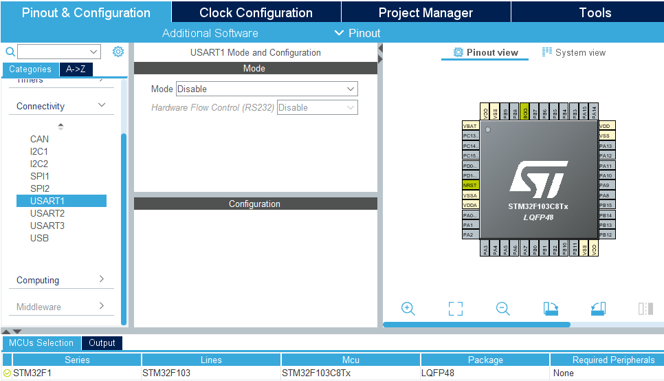
Here is the configuration tab for the USART module in CubeMX
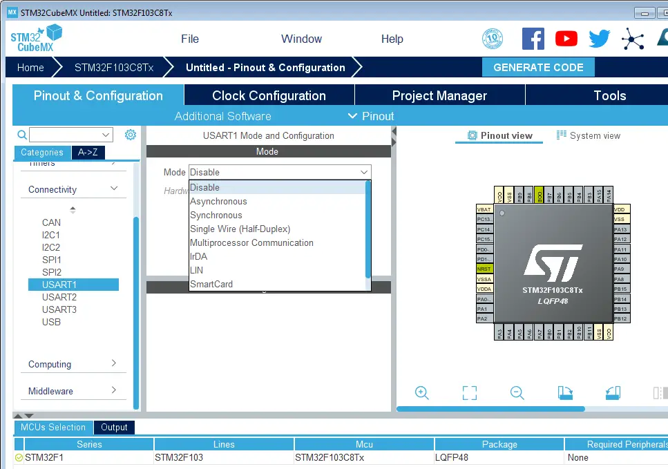
And here are the possible modes for USART that can be configured.
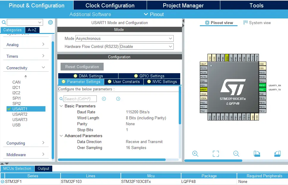
Let’s pick the asynchronous mode for example. You’ll find that now we’re able to set the baud rate, stop bits, parity control option, and other parameters. You can also enable/disable the USART data flow control. And USART interrupts from the NVIC interrupt controller parameters tab.
The STM32 HAL library provides us with a handful of functions to handle various UART operations (sending/receiving data, handling interrupts, DMA, etc). Below are the functions that you’ll most probably need in your projects. However, you can check the HAL firmware user manual for an exhaustive list of all UART HAL APIs.
HAL_UART_Transmit ( UART_HandleTypeDef * huart , const uint8_t * pData , uint16_t Size , uint32_t Timeout ) ;
HAL_UART_Receive ( UART_HandleTypeDef * huart , uint8_t * pData , uint16_t Size , uint32_t Timeout ) ;
The STM32 UART example below is a very basic test project that you can implement to get yourself started with the STM32 UART. It reads the incoming data (12 bytes) over the UART serial port and echo (transmit) it back to the terminal using the “polling” method.
To learn more about how this example code works, you can proceed to the next tutorials in this STM32 UART tutorial series (linked below)!
The next sections will help you learn theoretical information about the STM32 UART hardware and how it works internally. This will help you better understand how it works and how to configure the STM32 UART and optimize the performance of your target application. However, it’s not mandatory for everyone to study it in the meantime and you can now move on to the next part of this STM32 UART tutorial series.
You’ve almost completed the first part of This Multi-Part Tutorial Series: (1) STM32 UART Tutorial
![]()
The universal synchronous asynchronous receiver transmitter (USART) offers a flexible means of full-duplex data exchange with external equipment requiring an industry-standard NRZ (Non-Return-To-Zero) asynchronous serial data format. The USART offers a very wide range of baud rates using a fractional baud rate generator.
It supports synchronous one-way communication and half-duplex single-wire communication. It also supports the LIN (local interconnection network), Smartcard Protocol, IrDA (infrared data association) SIR ENDEC specifications, and modem operations (CTS/RTS). It allows multiprocessor communication. High-speed data communication is possible by using the DMA for multi-buffer configuration.
In this section, we’ll get a deep insight into the STM32 USART module hardware, its block diagram, functionalities, BRG, modes of operations, and data reception/transmission.
Any USART bidirectional communication requires a minimum of two pins: Receive Data In ( RX ) and Transmit Data Out ( TX ). Through these pins, serial data is transmitted and received in normal USART mode. The CK pin is required to interface in synchronous mode. The CTS & RTS pins are required in Hardware flow control mode.
As you can easily spot in the digital block diagram for this UART hardware module, there are two separate shift registers and double-buffered in/out data for a full-duplex data transmission and reception operation. Both shift registers which shift-in or out the data during reception/transmission are being clocked at the rate of the BRG (baud rate generator) circuitry at the bottom of the diagram.
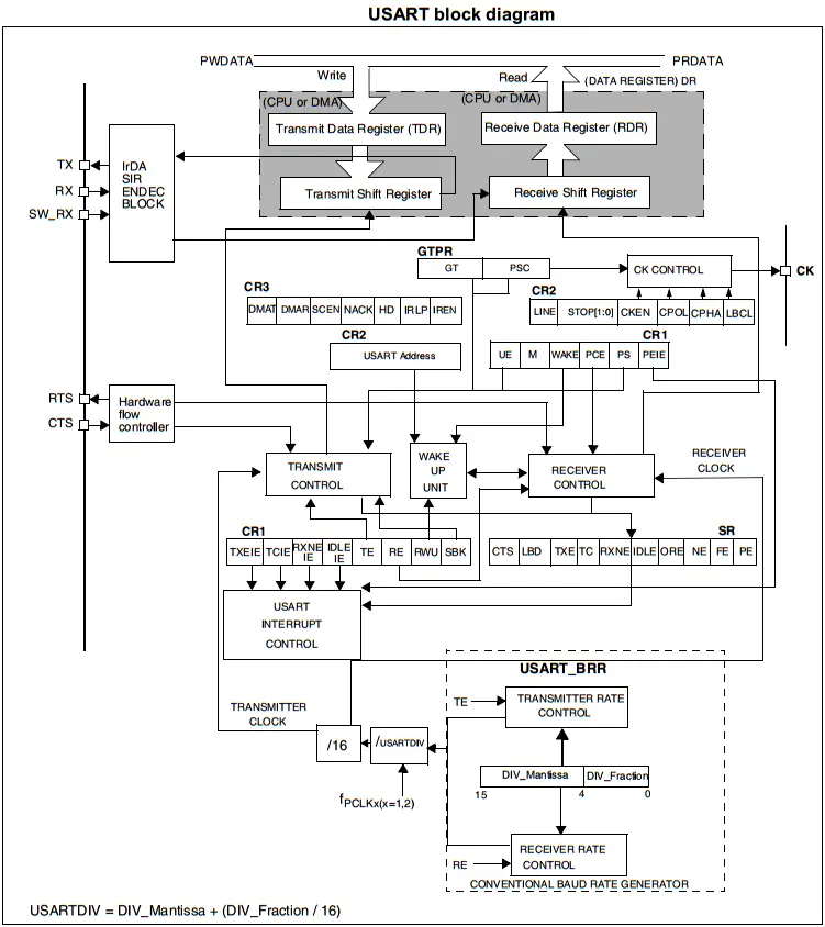
There is an address register for multi-processor communication mode. There exist a hardware data flow control unit to support this feature. And also an IrDA decoder circuitry, and interrupt control unit to generate various interrupt signals on different USART hardware events.
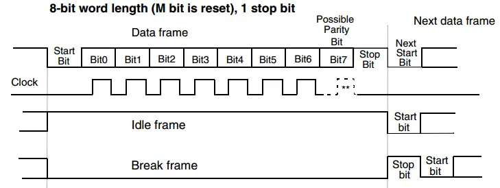
Word length may be selected as being either 8 or 9 bits by programming the M bit in the USART_CR1 register. Transmission and reception are driven by a common baud rate generator, the clock for each is generated when the enable bit is set respectively for the transmitter and receiver. The TX pin is in a low state during the start bit. It is in a high state during the stop bit.
An Idle character is interpreted as an entire frame of “1”s followed by the start bit of the next frame which contains data (The number of “1” ‘s will include the number of stop bits).
A Break character is interpreted on receiving “0”s for a frame period. At the end of the Break frame, the transmitter inserts either 1 or 2 stop bits (logic “1” bit) to acknowledge the start bit.
The USART transmitter can send data words of either 8 or 9 bits depending on the M bit status. When the transmit enable bit (TE) is set, the data in the transmit shift register is shifted out to the TX pin, and the corresponding clock pulses are output on the CK pin (for synchronous mode).
During a USART transmission, data shifts out the least significant bit first on the TX pin. Every character is preceded by a start bit, which is a logic level low for a one-bit period. The character is terminated by a configurable number of stop bits. The following stop bits are supported by USART: 0.5, 1, 1.5, and 2 stop bits.
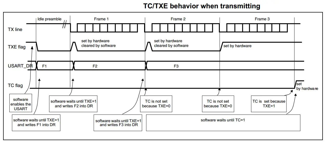
When a transmission is taking place, a write instruction to the USART_DR register stores the data in the TDR register and which is copied in the shift register at the end of the current transmission.
When no transmission is taking place, a write instruction to the USART_DR register places the data directly in the shift register, the data transmission starts, and the TXE bit is immediately set.
If a frame is transmitted (after the stop bit) and the TXE bit is set, the TC bit goes high. An interrupt is generated if the TCIE bit is set in the USART_CR1 register. After writing the last data into the USART_DR register, it is mandatory to wait for TC=1 before disabling the USART or causing the microcontroller to enter the low-power mode.
The TC bit can also be cleared by writing a ‘0’ to it.
The timing sequence diagram down below will show you the exact behavior of the USART transmitter hardware, the TC bit, and the TXE flag bit.
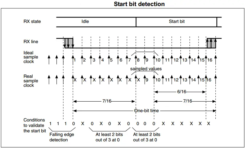
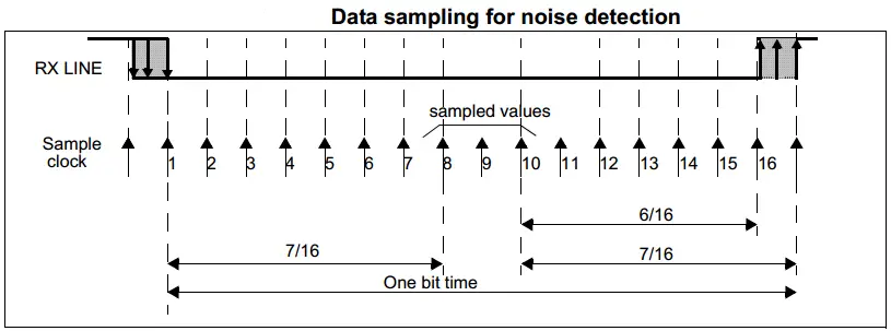
The USART can receive data words of either 8 or 9 bits depending on the M bit in the USART_CR1 register. In the USART, the start bit is detected when a specific sequence of samples is recognized.
This sequence is: 1 1 1 0 X 0 X 0 X 0 0 0 0. If the sequence is not complete, the start bit detection aborts and the receiver returns to the idle state (no flag is set) where it waits for a falling edge.
The receiver clock is x16 times faster than the transmitter clock which is generated by the same baud rate generator. Which guarantees more samples (typically 16) per bit-time duration. The diagram below shows you the start bit detection and the exact conditions that must be met to validate a true start bit.
During a USART reception, data shifts in the least significant bit first through the RX pin. In this mode, the USART_DR register consists of a buffer (RDR) between the internal bus and the received shift register.
When a character is received, The RXNE bit is set. It indicates that the content of the shift register is transferred to the RDR. In other words, data has been received and can be read (as well as its associated error flags). An interrupt is generated if the RXNEIE bit is set.
In multibuffer, RXNE is set after every byte received and is cleared by the DMA read to the Data Register. In single buffer mode, clearing the RXNE bit is performed by software read to the USART_DR register. The RXNE flag can also be cleared by writing a zero to it. The RXNE bit must be cleared before the end of the reception of the next character to avoid an overrun error.
The RE bit should not be reset while receiving data. If the RE bit is disabled during the reception, the reception of the current byte will be aborted.
The baud rate for the receiver and transmitter (RX and TX) are both set to the same value as programmed in the Mantissa and Fraction values of USARTDIV.

USARTDIV is an unsigned fixed-point number that is coded on the USART_BRR register. FCK is the input clock to the USART peripheral.
The baud rate counters are updated with the new value of the Baud registers after a write to USART_BRR. Hence the Baud rate register value should not be changed during communication.
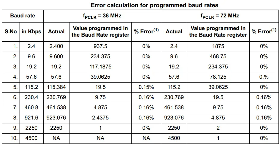
Down below is an example table from the datasheet for the error (percentage) in the baud rate at different rates with different clock frequencies for comparison.
The (Error%) is defined as (Calculated Baud Rate – Desired Baud Rate) / Desired Baud Rate.
Parity control (generation of parity bit in transmission and parity checking in reception) can be enabled by setting the PCE bit in the USART_CR1 register. Depending on the frame length defined by the M bit, the possible USART frame formats are as listed in the table down below.
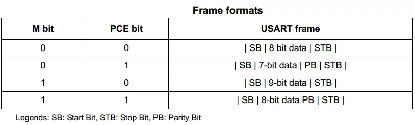
Even parity : the parity bit is calculated to obtain an even number of “1s” inside the frame made of the 7 or 8 LSB bits (depending on whether M is equal to 0 or 1) and the parity bit.
Odd parity : the parity bit is calculated to obtain an odd number of “1s” inside the frame made of the 7 or 8 LSB bits (depending on whether M is equal to 0 or 1) and the parity bit.
There is a possibility of performing multiprocessor communication with the USART (several USARTs connected in a network). For instance, one of the USARTs can be the master, its TX output is connected to the RX input of the other USART. The others are slaves, their respective TX outputs are logically ANDed together and connected to the RX input of the master.
In multiprocessor configurations it is often desirable that only the intended message recipient should actively receive the full message contents, thus reducing redundant USART service overhead for all non-addressed receivers.
The non-addressed devices may be placed in mute mode by means of the muting function.
The USART can enter or exit from mute mode using one of two methods, depending on the WAKE bit in the USART_CR1 register:
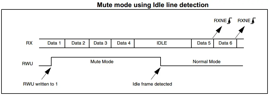
IDLE Line Detection (WAKE=0)
The USART enters mute mode when the RWU bit is written to 1. It wakes up when an Idle frame is detected. Then the RWU bit is cleared by hardware but the IDLE bit is not set in the USART_SR register. RWU can also be written to 0 by software.
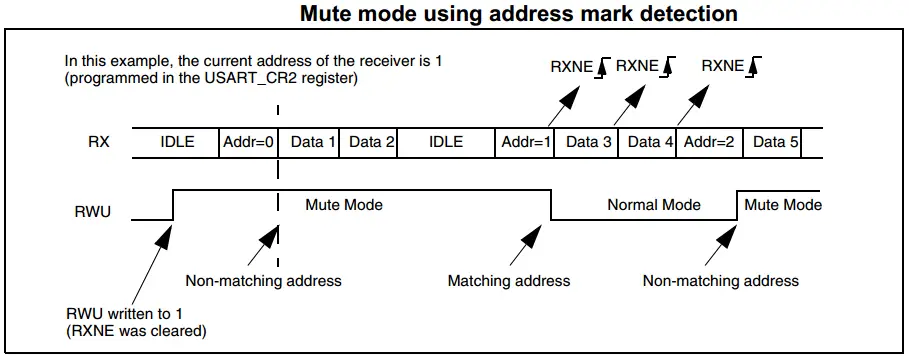
Address Mark Detection (WAKE=1)
In this mode, bytes are recognized as addresses if their MSB is a ‘1’ else they are considered as data. In an address byte, the address of the targeted receiver is put on the 4 LSB. This 4-bit word is compared by the receiver with its own address which is programmed in the ADD bits in the USART_CR2 register.
The USART enters mute mode when an address character is received which does not match its programmed address. In this case, the RWU bit is set by hardware. The RXNE flag is not set for this address byte and no interrupt nor DMA request is issued as the USART would have entered the mute mode.
It exits from mute mode when an address character is received which matches the programmed address. Then the RWU bit is cleared and subsequent bytes are received normally. The RXNE bit is set for the address character since the RWU bit has been cleared.
The RWU bit can be written to 0 or 1 when the receiver buffer contains no data (RXNE=0 in the USART_SR register). Otherwise, the write attempt is ignored.
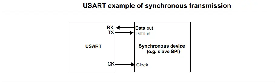
The USART allows the user to control bidirectional synchronous serial communication in master mode. The CK pin is the output of the USART transmitter clock. No clock pulses are sent to the CK pin during the start bit and stop bit. Depending on the state of the LBCL bit in the USART_CR2 register clock pulses will or will not be generated during the last valid data bit (address mark). The CPOL bit in the USART_CR2 register allows the user to select the clock polarity, and the CPHA bit in the USART_CR2 register allows the user to select the phase of the external clock.
During IDLE, preamble, and send break, the external CK clock is not activated. In synchronous mode, the USART transmitter works exactly like in asynchronous mode. But as CK is synchronized with TX (according to CPOL and CPHA), the data on TX is synchronous.
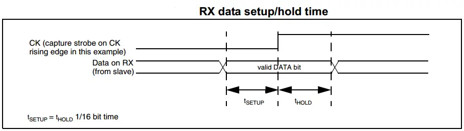
In this mode, the USART receiver works in a different manner compared to the asynchronous mode. If RE=1, the data is sampled on CK (rising or falling edge, depending on CPOL and CPHA), without any oversampling. A setup and a hold time must be respected (which depends on the baud rate: 1/16 bit time).
The CK pin works in conjunction with the TX pin. Thus, the clock is provided only if the transmitter is enabled (TE=1) and data is being transmitted (the data register USART_DR has been written). This means that it is not possible to receive synchronous data without transmitting data.
The single-wire half-duplex mode is selected by setting the HDSEL bit in the USART_CR3 register. In this mode, the following bits must be kept clear (0):
LINEN and CLKEN bits in the USART_CR2 register,
SCEN and IREN bits in the USART_CR3 register.
The USART can be configured to follow a single-wire half-duplex protocol. In single-wire half-duplex mode, the TX and RX pins are connected internally. The selection between half and full-duplex communication is made with a control bit ‘HALF DUPLEX SEL’ (HDSEL in USART_CR3).
Apart from this, the communications are similar to what is done in normal USART mode.
The USART hardware in STM32 microcontrollers is capable of detecting 4 errors in operations. These error signals are as follows.
Overrun Error
An overrun error occurs when a character is received when RXNE has not been reset. Data can not be transferred from the shift register to the RDR register until the RXNE bit is cleared.
Noise Error
Over-sampling techniques are used (except in synchronous mode) for data recovery by discriminating between valid incoming data and noise.
The NE bit is reset by a USART_SR register read operation followed by a USART_DR register read operation.
Framing Error
A framing error is detected when: The stop bit is not recognized on reception at the expected time, following either a desynchronization or excessive noise.
When the framing error is detected:
The FE bit is reset by a USART_SR register read operation followed by a USART_DR register read operation.
Parity Check Error
When a parity error is detected in the received data frame, the PE bit is set and it’ll fire an interrupt if it’s enabled. It can be set to even or odd parity depending on the application and whether it’s implemented in the communication or not. We won’t be using the parity check in all the tutorials and LABs dealing with USART.
It is possible to control the serial data flow between two devices by using the CTS input and the RTS output. RTS and CTS flow control can be enabled independently by writing respectively RTSE and CTSE bits to 1 (in the USART_CR3 register). The diagram below shows how to connect two devices in this mode.
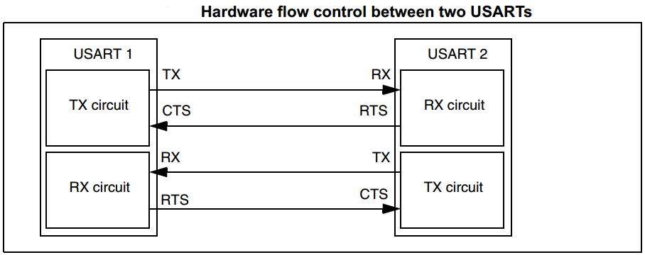
RTS Flow Control
If the RTS flow control is enabled (RTSE=1), then RTS is asserted (tied low) as long as the USART receiver is ready to receive new data. When the receive register is full, RTS is de-asserted, indicating that the transmission is expected to stop at the end of the current frame.
CTS Flow Control
If the CTS flow control is enabled (CTSE=1), then the transmitter checks the CTS input before transmitting the next frame. If CTS is asserted (tied low), then the next data is transmitted (assuming that data is to be transmitted, in other words, if TXE=0), else the transmission does not occur. When CTS is de-asserted during a transmission, the current transmission is completed before the transmitter stops.
The LIN (Local Interconnection Network) Mode is selected by setting the LINEN bit in the USART_CR2 register.
LIN Data Transmission
LIN Data Reception
A break detection circuit is implemented in the USART. The detection is totally independent of the normal USART receiver. A break can be detected whenever it occurs, during idle state or during a frame.
When the receiver is enabled (RE=1 in USART_CR1), the circuit looks at the RX input for a start signal. The method for detecting start bits is the same when searching break characters or data. After a start bit has been detected, the circuit samples the next bits exactly like for the data (on the 8th, 9th and 10th samples). If 10 (when the LBDL = 0 in USART_CR2) or 11 (when LBDL=1 in USART_CR2) consecutive bits are detected as ‘0’, and are followed by a delimiter character, the LBD flag is set in USART_SR. If the LBDIE bit=1, an interrupt is generated.
Before validating the break, the delimiter is checked for as it signifies that the RX line has returned to a high level. If a ‘1’ is sampled before the 10 or 11 have occurred, the break detection circuit cancels the current detection and searches for a start bit again.
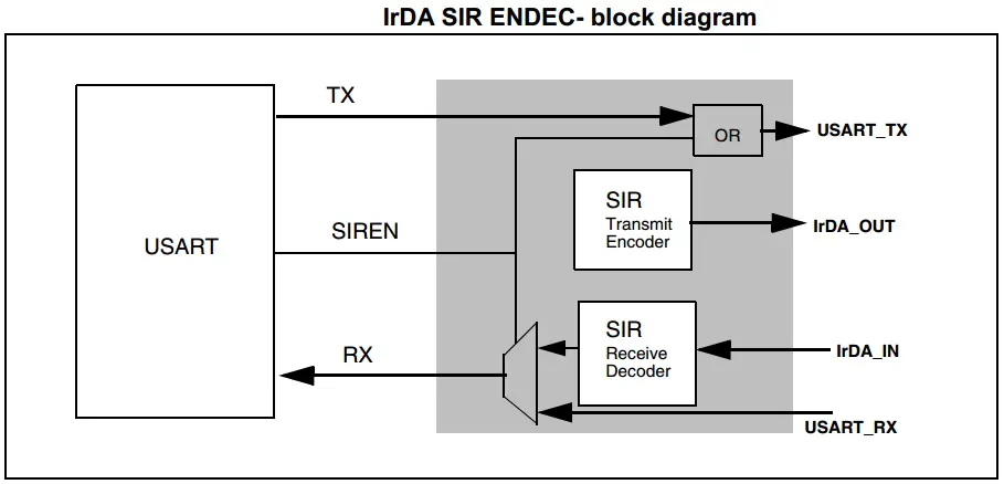
The IrDA mode is selected by setting the IREN bit in the USART_CR3 register. In IrDA mode, the following bits must be kept clear (0):
The IrDA SIR physical layer specifies the use of a Return to Zero, an Inverted (RZI) modulation scheme that represents logic 0 as an infrared light pulse.
The SIR Transmit encoder modulates the Non-Return to Zero (NRZ) transmit bitstream output from USART. The output pulse stream is transmitted to an external output driver and infrared LED. USART supports only bit rates up to 115.2Kbps for the SIR ENDEC. In normal mode, the transmitted pulse width is specified as 3/16 of a bit period.
The SIR receive decoder demodulates the return-to-zero bitstream from the infrared detector and outputs the received NRZ serial bit stream to USART. The decoder input is normally HIGH (marking state) in the idle state. The transmit encoder output has the opposite polarity to the decoder input. A start bit is detected when the decoder input is low.
To get an idea of what configuration modes are supported in which USART module in the target MCU you’re using, you’ll have to check out the datasheet for it. You’ll find a table like the one shown below, highlighting which modes are supported in each USART module.
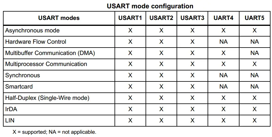
For the STM32F103C8 microcontroller in the blue pill board we’re using, there are only 3 USARTs.
For the STM32L432KC microcontroller in the Nucleo32-L432KC board we’re using, there are only 3 USARTs.
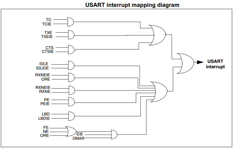
The USART interrupt events are connected to the same interrupt vector. So the USART fires a single interrupt signal regardless of the source of it. The software will have to detect it.
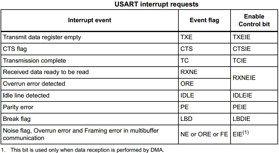
These events generate an interrupt if the corresponding Enable Control Bit is set. The diagram down below shows this interrupt signals mapping to only one request line.
To conclude this STM32 UART ultimate guide tutorial, we can say that we’ve explored the hardware features of the STM32 UART peripheral and its different operating modes. In the next tutorials of this series, we’ll explore the STM32 UART features & modes one by one to implement some example projects for each to get the hang of it and make sure you completely understand how and when to use each feature/configuration/mode of the STM32 UART.
You can now proceed to the other parts of this STM32 UART Tutorial Series.
Stay Updated With All New Content Releases. You Also Get Occasional FREE Coupon Codes For Courses & Other Stuff!